Frequency converters
Frequency converters general information
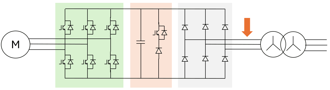
A typical frequency converter (FC) nowadays is a so-called voltage-source type - over 95% of all FC are voltage-source converters (VSC). This FC type has a DC-link with a capacitor bank across (see Fig.1).
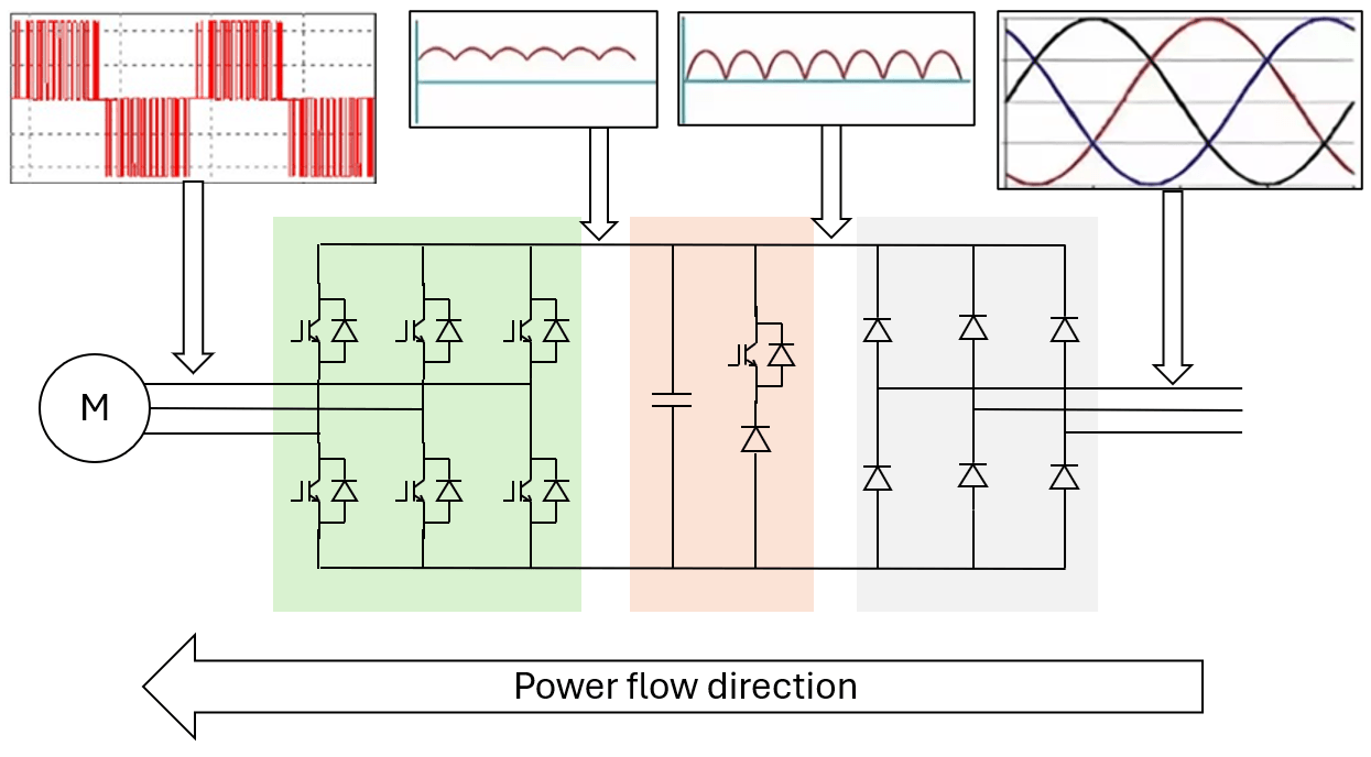 Fig.1. VSC topology.
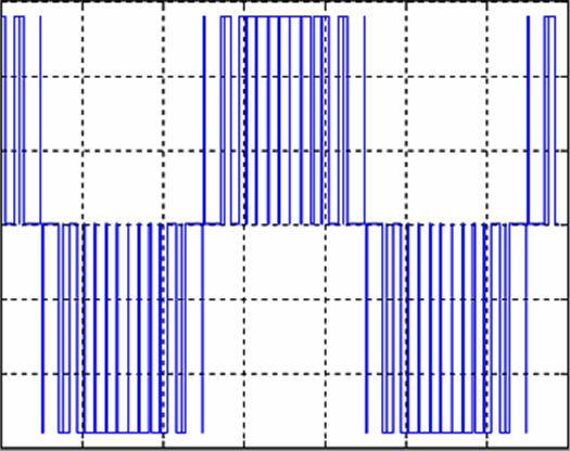
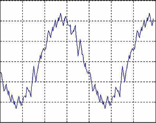
The voltage of the supply network with a constant frequency and amplitude is first rectified into DC voltage though with some ripples (Fig.2), and then it is converted into the voltage with the required frequency and amplitude (Fig. 3). Note that the voltage waveform is made of pulses of varying duration, wherein the "fundamental" voltage is sinusoidal.
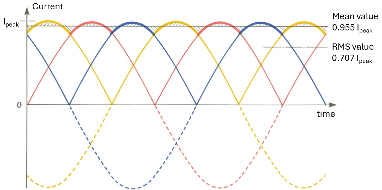 Fig.2. Rectified current in
the DC link.
Fig.2. Rectified current in
the DC link.
 (a)
(a)
 (b)
(b)
Fig.3. Phase voltage (a) and current (b) at the converter output (machine side).
Some FC theory can be found for example here, here and here.
FC mounting variant
Small and light FC are usually wall-mounted, while large and heavy are - floor-mounted. In Fig.4 the smaller dark-colored FC are for wall-mounting. The larger light-colored FC should be floor-installed. Usually FC above 250 kW can be found in floor-mounted versions only. FC can be wall mounted when powers are below 250 kW. Wall-mounted modules can be convenient in certain cases, e.g. FC can be installed into existing cubicles or when the floor is wet wall mounted design can be the only way. For some powers (usually 200...250 kW) there exists both wall-mounted & floor-mounted versions.
FC topologies
FC can be 2-quadrant (2Q) and 4-quadrant (4Q):
- 2Q FC can transfer power only in one direction - from the grid to the electric machine (motor),
- 4Q FC can transfer power not only from the grid to the machine but also from the machine (generator) to the grid.
Usually the operational mode (motoring, generating or both) of the application defines what FC should be chosen, 2Q or 4Q. For example a wind turbine requires 4Q FC with fully-controlled inventor scheme at the grid side. Sometimes operational requirements in applications which typically require 2Q, may require 4Q - for example large fan with high inertia may require considerable braking capability to slow down in reasonably short time.
FC can be low-voltage (LV) and medium-voltage (MV). LV FC usually have only 2-level (2L) topology, MV - several alternative topologies (3L-NPC, SCHB, etc.). Both the LV and MV topologies can be 2Q and 4Q.
The choice of LV or MV is usually defined by the power level, but other features of the application, e.g. long cable can also affect the choice.
Some FC require input transformer, some don't.
As in DriveConstructor we deal with VSC only, all the topologies included in the software and presented below have "VSC" in the designations.
Converters of 2-level topology
2Q-2L-VSC-6p, 2Q-2L-VSC-12p and 4Q-2L-VSC
2Q FC inventor scheme at the grid side can be 6-pulse ("6p") and 12-pulse ("12p"). Difference between "6p" and "12p" is in size, weight, cost, efficiency and influence on the grid (THD). 4Q FC is larger, heavier, more expensive and has lower efficiency than 2Q FC. 4Q produce lower THD in the grid. 2-level FC are usually LV.
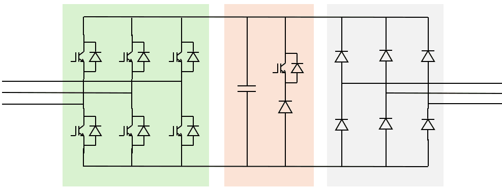 Fig.4a. 2Q-2L-VSC-6p.
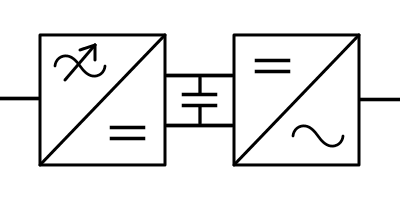 Fig.4b. Icon designation.
Note that on Fig.4a motor side of the FC is the right side, while on Fig.4b - left side.
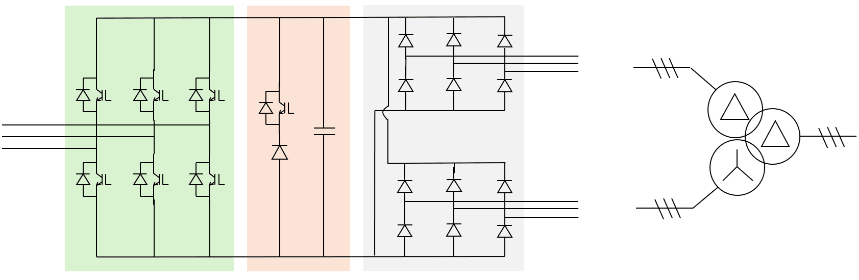 Fig.5a.
2Q-2L-VSC-12p.
Fig.5a.
2Q-2L-VSC-12p.
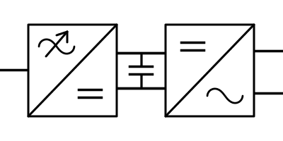 Fig.5b. Icon designation.
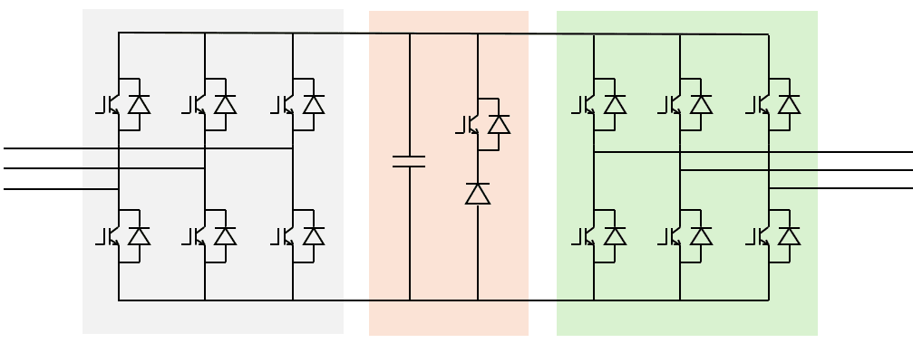 Fig.6a. 4Q-2L-VSC.
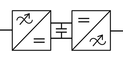 Fig.6b. Icon designation.
Converters with 3- and multi-level topologies
2Q-3L-NPC-VSC and 4Q-3L-NPC-VSC
3-level FC are usually MV. NPC stands for Neutral-Point Clamped.
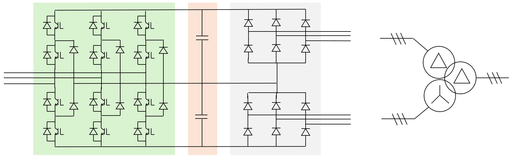 Fig.7a.
2Q-3L-NPC-VSC.
Fig.7a.
2Q-3L-NPC-VSC.
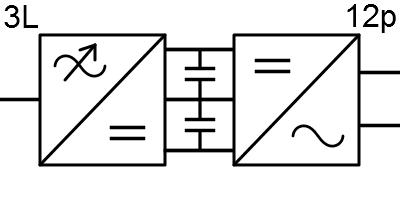 Fig.7b. Icon designation.
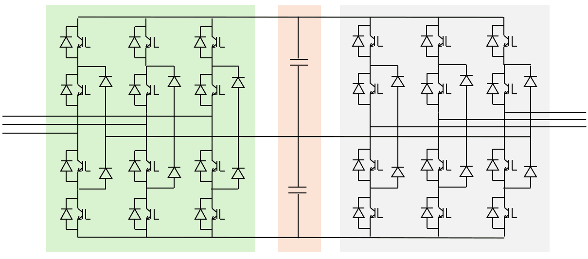 Fig.8a. 4Q-3L-NPC-VSC.
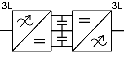 Fig.8b. Icon designation.
2Q-ML-SCHB-VSC and 4Q-ML-SCHB-VSC
SCHB stands for Series-Connected H-Bridge.
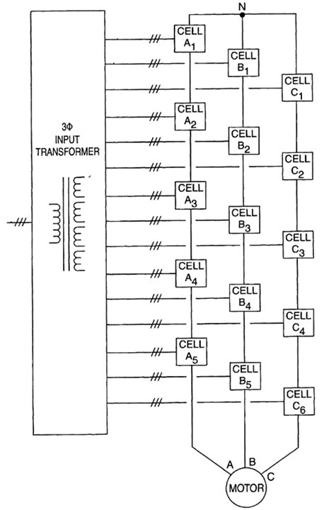 Fig.9a. 2Q-ML-SCHB-VSC topology.
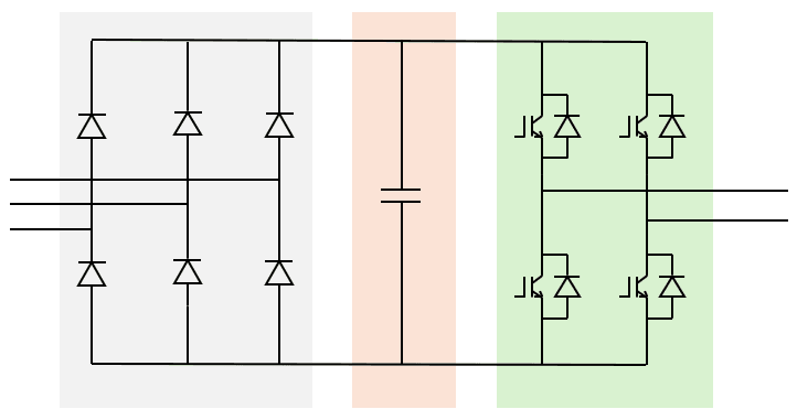 Fig.9b. 2Q-ML-SCHB-VSC cell.
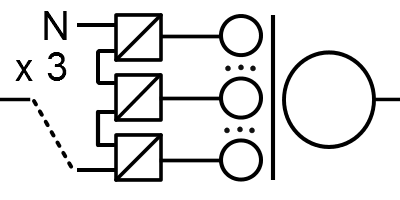 Fig.9c. Icon designation.
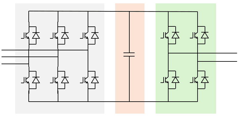 Fig.9d. 4Q-ML-SCHB-VSC cell.
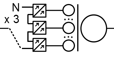 Fig.9e. Icon designation.
FC power, voltage and current
Rated power
FC are rated according to IEC standard. The series of powers in DriveConstructor is 1.1, 1.5, 2.2, 3, 4, 5.5, 7.5, 11, 15, 18.5, 22, 30, 37, 45, 55, 75, 90, 110, 132, 160, 200, 250, 280, 315, 355, 400, 450, 500, 560, 630, 710, 800, 900, 1000, 1250, 1400, 1600, 2000, 2500, 3150, 4000 kW. If it is desirable that power is chosen automatically then choose "any" - it is the default setting.
Rated voltage
The same voltage ranges are given both for grid side and machine side of the converter. In DriveConstructor the variants to choose from are: 380-440, 650-700, 3200-3400, 5900-6700, 9000-12000 V. If it is desirable that voltage is chosen automatically then choose "any" - it is the default setting.
In DriveConstructor 3L-NPC topologies can have voltage rating of 2460 V, 3300 V and 4160 V, while ML-SCHB topologies - 6000 V, 6600 V, 10000 V and 11000 V.
Currents
For almost any application it can be expected that load torque will vary with time going up and down. The pattern can be quite unpredictable. As current drawn from the FC is proportional to the load torque, the torque variation determines the current variation. In some application, e.g. pumps, the variation is not significant and can be called "low", while in other applications, e.g. conveyor or winch, the variation can be significant, and, therefore can be called "high". Examples of what can be called "high overloads" and "low overloads" are presented in Fig.10.
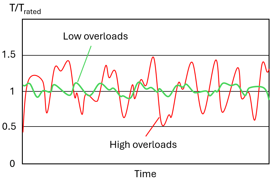 Fig.10. "High overloads" and "low
overloads".
Fig.10. "High overloads" and "low
overloads".
Choosing the FC the designer should take this aspect into account. Each FC has certain overload capability determined by several physical limitations such as thermal current and maximum current. The overloads the FC can tolerate will be characterized by a certain amplitude, duration and cycle.
The same converter can be used for "high overloads (HO)" and "low overloads (LO)" but its rated current in a catalogue will be presented in two variants; and , where is always higher than . The principle is that motor current should be lower than FC current. When choosing FC for LO application, e.g. a pump, should be used and should be higher than . Usually for LO applications acceptable overloads are just 10% and FC current should then handle . When choosing FC for HO application, e.g. a conveyor, should be used and should be higher than . Usually for HO applications acceptable overloads are 50% and FC current should then handle .
Explanation is presented in Fig.10. Note which is rated continuous current, which is not used in practice. Short-term (10 s) high current of up to 200% of is acceptable for any converter.
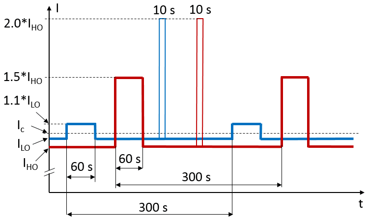 Fig.10a. Current overloads of
conventional FC.
Fig.10a. Current overloads of
conventional FC.
FC cooling
Typical efficiency of the low-voltage FC is 98% meaning 2% of converted energy is turned into heat which needs to be removed from the enclosed area. FC can be cooled by moving air and water (air- and liquid-cooling; AC and LC). The difference between AC and LC-cooled FC is in size and weight - higher compactness and lower weight can be achieved by use of liquid (water) cooling. AC and LC(=WC) FCs are usually priced on the same level.
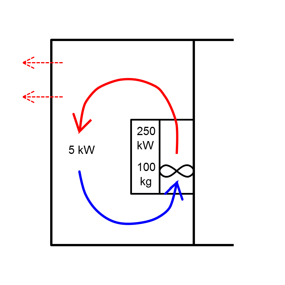
Fig.1 depicts a 250 kW low-voltage FC mounted on the wall in an enclosed area such as an electrical room.
 (a)
(a)
 (b)
(b)
 (c)
(c)
Fig.11. Cooling types.
With the efficiency of 98% the 250 kW FC will produce 5 kW of heat. To remove the heat from the FC's heatsink a quite powerful ventilation fan should be integrated into the FC enclosure. For the 250 kW power the volume of air pumped through the heatsink should be in the order of 2000-3000 m3/h. Filtering may be required if the environment is dusty or dirty. This can be a maintenance concern.
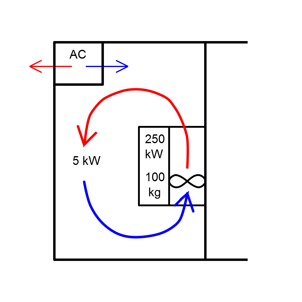
If the produced heat is not handled (removed) in some way, eventually the temperature within the enclosed area (ambient temperature for the FC) will increase. Increasing the ambient operating temperature above the maximum design temperature of the FC will cause the FC to overheat which shortens its lifetime and will cause shutdowns. In Fig.1,a the heat is removed in a natural way, e.g. through walls, windows, doors. This is possible if the enclosed area is large (e.g. large production hall). In Fig.1,b the heat is removed with the help of air conditioning. The latter measure can be costly and/or complicated to implement.
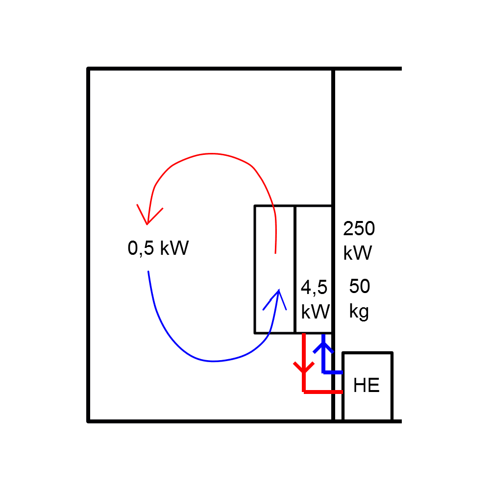
Fig. 1,c depicts water-cooled FC with water pipes going to the neighboring room. First, the water-cooled FC is considerably smaller (half the weight of the air-cooled one). Secondly, the heat produced inside the FC due to losses is divided into two parts; 90% is removed from the heat sink by the cooling water and brought away from the enclosed area where the FC is installed, 10% are dissipated within the enclosed area. The 10% of 5 kW of heat make just 500 W, which can be easily dissipated without additional measures like air conditioning. So, the largest portion of heat is removed through the liquid and can be transferred to another media through a heat exchanger as shown in Fig.1,c.
Liquids used in the FC primary cooling loop. Typical: drinking water, demineralized or deionized water, and a water/glycol mixture for freeze protection.
Heat exchangers
If clean cooling water is not available on site, water-to-air or water-to-water heat exchanger may be used, providing clean water. Parameters of the heat exchanger such as size, weight, cost and losses need to be included in the system parameters/ performances when benchmarking alternative systems (cooling solutions). Liquid to liquid (water-to-water) heat exchangers are used when a cooling liquid is readily available. Liquid to air (water-to-air) heat exchangers are used primarily when air conditioning is not desired, or in dusty/dirty environments where air cooled VFD's can be adversely affected by these conditions (plugged heat sinks, electronics covered in dust, complicated maintenance routines. Challenges of water cooling: condensation, electrochemical corrosion (mostly related to HEx)
Other factors to consider:
- Relation between cooling and IP
- Audible noise. The large fan is the primary reason air cooled FCs are noisy. There is no large air fan in LC FC, just a very small fans to cool the electronic boards
Recommended description by Siemens
Filters
In many cases FC should be equipped with either input or output filters. Filters can help to solve various EMC issues on both grid side and machine side. However, the pay is extra size, weight, cost and losses. Some MV topologies do not require output filters. In DC it is possible to choose "choke" and "choke+RFI" for input filter and du/dt filter and sin-filter for output filter.
Output filters
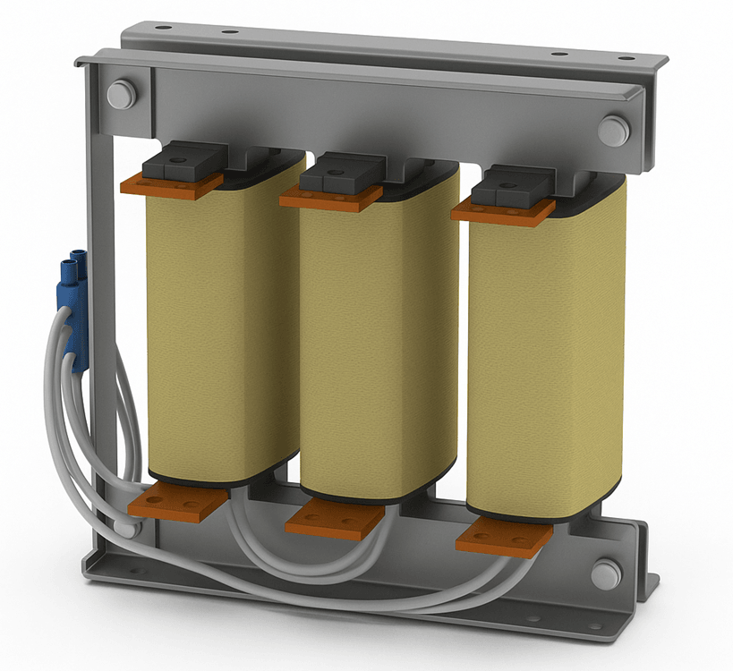
SIN-filter
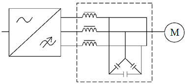
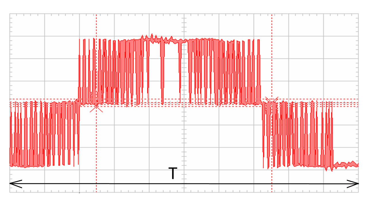
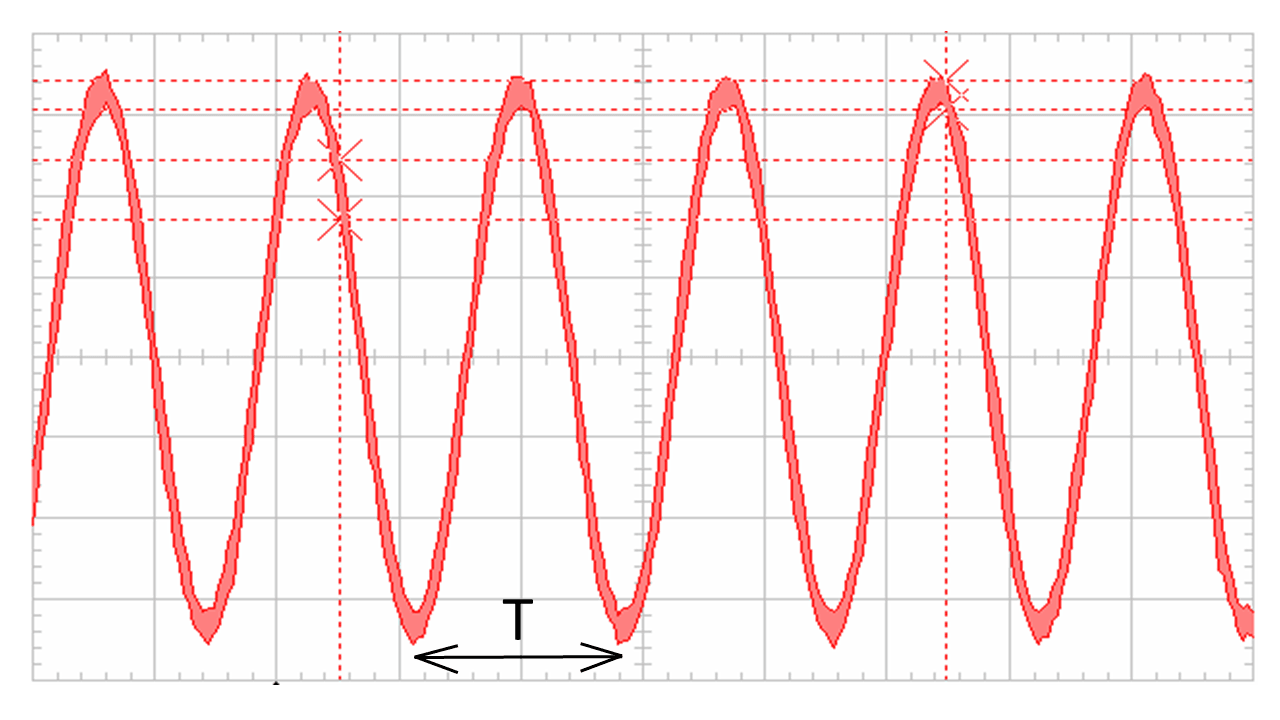
The LC filter, called the "sinus filter", "sine-filter" or "sin filter" (Fig. 1) is the most efficient filter in terms of turning the current and voltage waveforms that the FC produces into almost sinusoidal form. Fig. 2 shows an example of the effect of a sin-filter on the shape of the voltage waveform at the FC output. With the use of a sin-filter, virtually all the negative effects described in chapter FC influence on the electric machine are eliminated, since the machine is powered by voltage and current with a shape very close to sinusoidal.
 (a)
(a)
 (b)
(b)
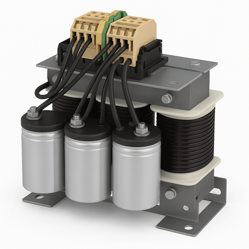
Fig. 12. "Classical" sin-filter topology (a) and product example (b).
 (a)
(a)
 (b)
(b)
Fig. 13. The voltage waveforms at the input (a) and at the output (b) of the sin-filter. Note different time span on the oscillograms.
Sin-filters have certain drawbacks (largely due to the high inductance value of its chokes):
- The voltage drop in the filter is 3-10%, depending on the manufacturer, the nominal power (current) of the filter and the frequency of the PWM.
- Losses of 0.5-2%. The more power, the lower the relative losses in the filter.
- Displacement of the field weakening point by 1-2 Hz towards low frequencies.
- Significant reduction (up to 20% or more) of the critical moment (overload capacity) of the machine.
Also it should be noted that the sine-filter is quite an expensive device. Its cost can be up to 30-40% of the cost of the FC (at low power - up to 50-70%).
du/dt-filter
Structurally, the du/dt filter is a three-phase choke (Fig. 14,a), and from the point of view of the electric circuit theory it is a concentrated inductive resistance. The inclusion of inductance in the equivalent electrical circuit of the cable increases the wave resistance of the cable line and brings down the reflection coefficient. Thus, the voltage peaks at terminals decreases.
 (a)
(a)
 (b)
(b)
Fig. 14. "Classical" du/dt-filter topology (a) and product example (b).
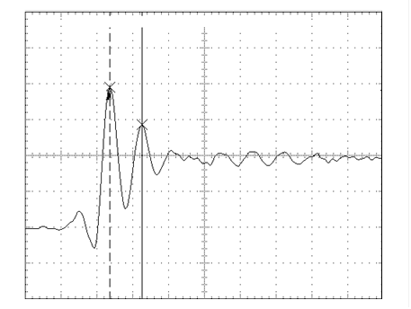
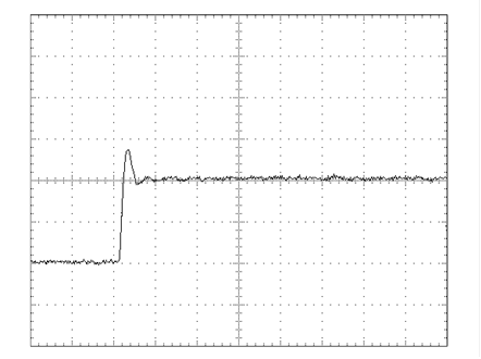
However, the main purpose of du/dt-filters is to eliminate du/dt-effect, i.e. decrease in the rise time of the voltage pulse. In addition, due to the inertial properties of the inductance, the filter also reduces the voltage surge at the leading edge of the pulse (Fig.15). The length of the cable is 30 m. Note different rise time: dt=220 ns, dt=820 ns.
 (a)
(a)
 (b)
(b)
Fig. 15. Voltage pulses at the machine terminals without du/dt-filter (a) and with a filter (b).
Common recommendations on the use of du/dt-filters and other measures
To reduce the overvoltages, du/dt-effect and bearing currents, a whole complex of measures is often applied, including both recommendations to machine manufacturers, and the use of various filters, special cables, etc. The measures depend in particular on the voltage level of the mains and on the power (size) of the machine. Different drive manufacturers can offer different measures. One example is presented in the table:
| < 100 kW | >= 100 kW | >= 350 kW | |
|---|---|---|---|
| Standard machine | Standard machine + isolated N-bearing | Standard machine + isolated N-bearing + ferrite rings | |
| (Standard machine + du/dt-filter) or Reinforced insulation | (Standard machine + du/dt-filter) or (Reinforced insulation + isolated N-bearing) | (Standard machine + isolated N-bearing + du/dt-filter + 1 ferrite ring) or (Reinforced insulation + isolated N-bearing + ferrite rings) | |
| Reinforced insulation + du/dt-filter | Reinforced insulation + du/dt-filter | Reinforced insulation + isolated N-bearing + du/dt-filter + 1 ferrite ring |
Grid filters
Chokes
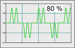
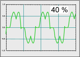
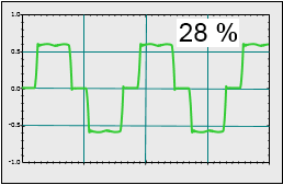
Influence of presence of the choke and its size on the harmonics injected into the grid is presented in Fig.16 and 17. The graphs show current waveform and the value of current distortion THD(i) as % of nominal current at full load.
 (a)
(a)
 (b)
(b)
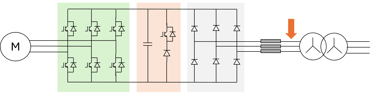
Fig. 16. 6-pulse rectifier without any choke (a) and current waveform for this topology (b).
 (a)
(a)
 (b)
(b)
 (c)
(c)
Fig. 17. 6-pulse rectifier with a choke (a) and current waveforms for small choke (b) and big choke (c).
LCL filter
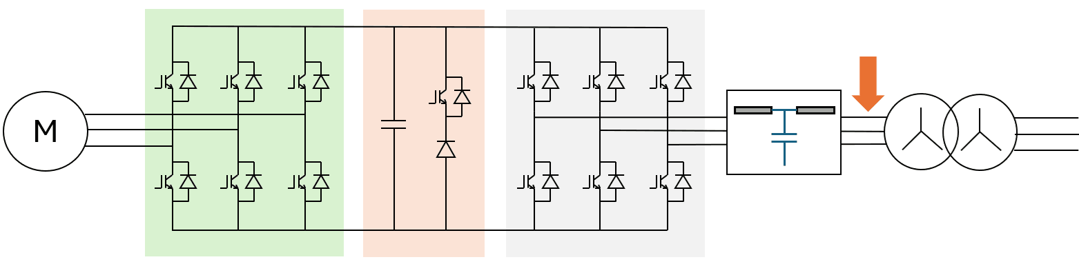
FC with LCL filter between FC and the grid is presented in Fig.7,a. Current waveform is very close to sinusoidal as can be seen in Fig. 7,b.
 (a)
(a)
 (b)
(b)
Fig. 18. Topology (a) and current waveform (b).
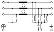
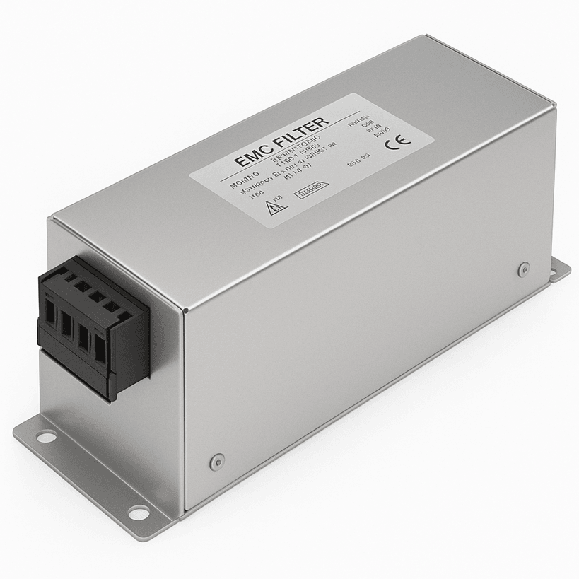
EMC filters
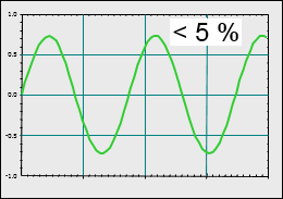
EMC filters (Fig.19) is destined for emission reduction in MHz range. Example of the effect is presented in Fig.20.
 (a)
(a)
 (b)
(b)
Fig. 19. EMC filters: topology (a), AC side filter product example (b).
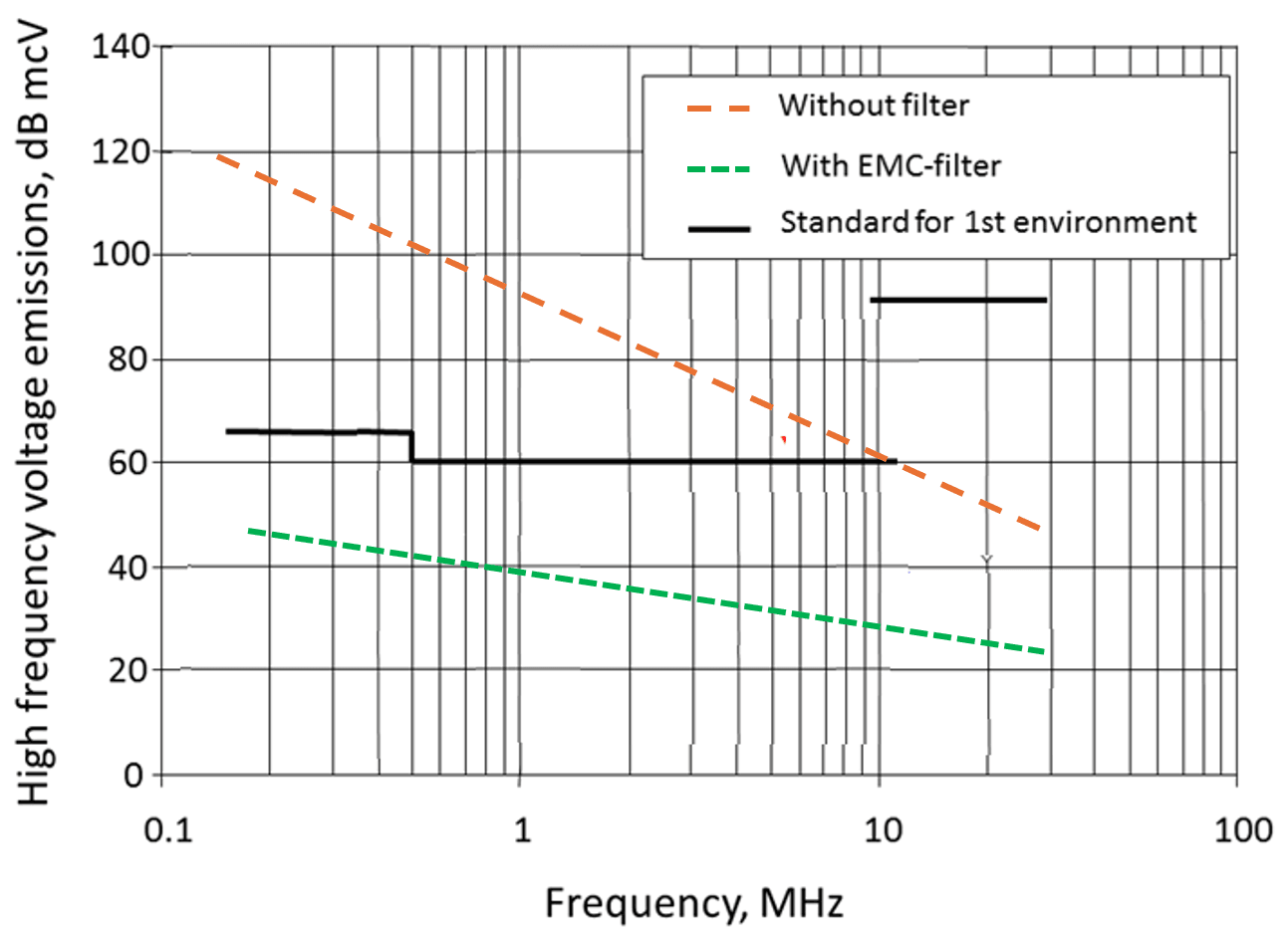
Fig. 20. Effect of use of EMC-filter.