Electric machines
Relevant information
What is included
Only rotating AC machines with cylindrical cores with inner rotor are included into this version of DriveConstructor. It is possible to choose between:
- SCIM - Squirrel Cage Induction Machine (Fig.1),
- SyRM - Synchronous Reluctance Machine (Fig.2),
- PMSM - Permanent Magnet Synchronous Machine (rotor shown in Fig.3).
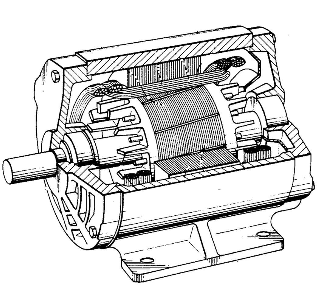 Fig.1A. SCIM.
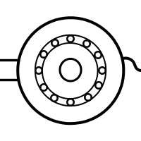 Fig.1B. icon of SCIM.
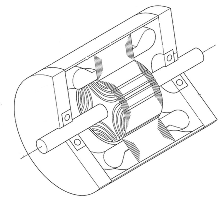 Fig.2A. SyRM.
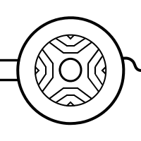 Fig.2B. icon of SyRM.
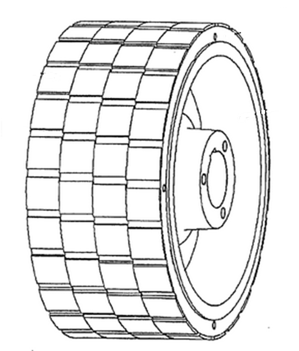 Fig.3A. Rotor of PMSM.
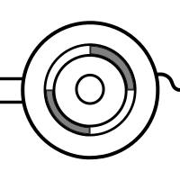 Fig.3B. icon of PMSM.
SCIM, PMSM and SyRM can be selected for any application and any drive train topology. SyRM are available for quite limited range of powers. So far only LV SyRM products are known, therefore only LV FC can be used to drive SyRM.
Performances of the machines of different types are different. Usually:
- Efficiency (SCIM) < Efficiency (SyRM) < Efficiency (PMSM)
- Cost (SCIM) < Cost (SyRM) < Cost (PMSM)
- Size (SCIM) > Size (SyRM) > Size (PMSM)
Key parameters of electric machines
Rated power
Power rating of the electric machines available in DriveConstructor is according to IEC 60072-1 which suggests the following preferred ratings (based on a subset of the R40 series) for motors (in kW) and generators (in kVA):
Note that asterix-marked powers are "secondary series" ratings and are only to be used in cases of special need.
In DriveConstructor we use the following series of powers (in kW): 1.1, 1.5, 2.2, 3, 4, 5.5, 7.5, 11, 15, 18.5, 22, 30, 37, 45, 55, 75, 90, 110, 132, 160, 200, 250, 280, 315, 355, 400, 450, 500, 560, 630, 710, 800, 900, 1000, 1250, 1400, 1600, 2000, 2500, 3150, 4000.
Our list is shorter than the IEC one as we picked up only the most used powers.
Rated voltage
Electric machines may be designed for different supply voltages (from converter or grid). Machines are usually designed for "standard" ranges of rated voltage, e.g. 380-400 V or 650-700 V, as it is easier to connect a "standard" machine to a typical grid or a "standard" frequency converter. In Europe and America the standard ranges are different. In Europe it is usual to differentiate between LV (below 1 kV) and MV (above 1 kV).
In DriveConstructor the range of rated voltages to which the machine is designed to operate within can be chosen from the following options: 380-440, 650-700, 3200-3400, 5900-6700, 9000-12000 V. If it is desirable that the voltage is chosen automatically then choose "any". It is assumed that all machines are Y-connected. In practice windings can be reconnected into D, but this option is not included.
Machines designed for lower voltage are usually smaller, lighter and cheaper than those designed for MV. This is because of thinner insulation in the slots, which allows putting more copper in the slots and makes heat removal easier.
It is normally not possible to design LV machines for very high powers as currents would become too high and cables would become too thick to be practical. LV machines are normally produced for powers from fractions of kW up to a few MW (in DriveConstructor up to 2 MW), MV machines - from about 0,2 MW to 10...20 MW (in DriveConstructor up to 5 MW), in some cases up to 100 MW!
Slot designs of LV and MV machines look quite different:
 Fig.4. LV slot.
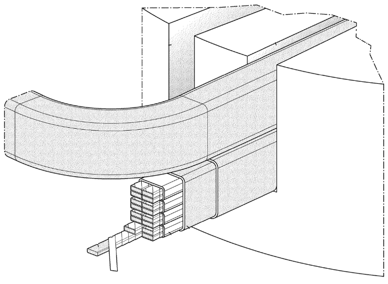 Fig.5. HV slot.
Rated synchronous speed
Rated synchronous speed is proportional to supply frequency and reverse proportional to number of poles (). For 50 Hz supply and number of poles 2, 4, 6, 8 and 10 rated synchronous speed is 3000, 1500, 1000, 750 and 600, respectively.
SCIM have slip, so its rated speed is lower than rated synchronous speed by a few percent. SyRM and PMSM have rated speed equal rated synchronous speed.
It is obvious that a machine designed for delivering high power is bigger than a machine designed for delivering low power. It is less obvious that the rated speed the machine is designed for affects it's weight, compactness, rotor inertia and cost. However, if the power is fixed, the machine with lower speed will have higher torque (). To be able to provide higher torque the machine has to be larger, heavier and as the consequence more expensive.
Efficiency class
The International Electrotechnical Commission (IEC) has developed an internationally applicable testing Standard IEC 60034-2-1 for electric motors and a classification scheme IEC 60034-30-1 with four levels of motor efficiency ("IE-code"):
- IE1 Standard efficiency,
- IE2 High efficiency,
- IE3 Premium efficiency
- IE4 Super premium efficiency.
The IE-code and its efficiency levels create a basic vocabulary for governments to determine the efficiency level for their minimum energy performance standards (MEPS). The European Union sets motor MEPS levels (Directive 640/2009) at IE3 (or IE2 in combination with a variable frequency drive) from 2015 for smaller motors and from 2017 covering also larger motors.
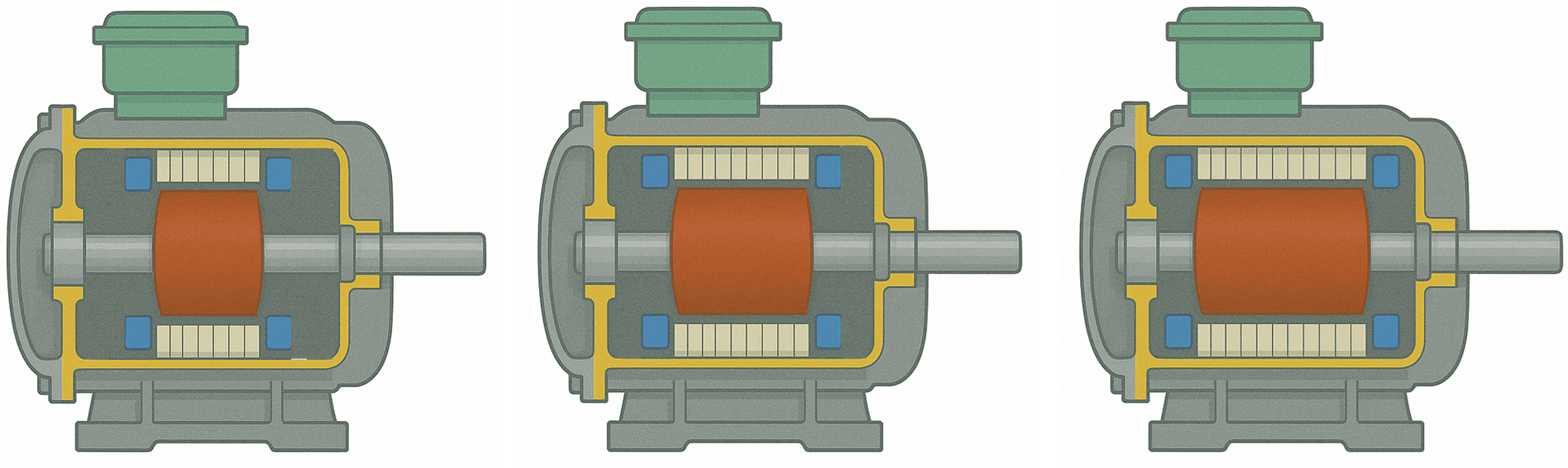
Fig.6. Cut-away of standard, energy-efficient, and premium efficiency motors.
Efficiency value for a certain class depends on power as shown on the diagram below:
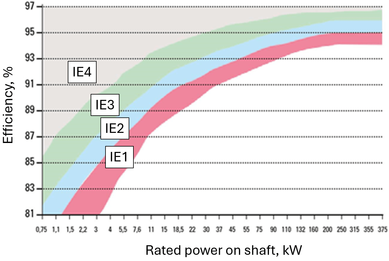
Fig.7. Efficiency classes for 4-pole motors.
Efficiency at partial load (e.g. 25%, 50%) is lower than at rated load (100%). High efficiency class motors are larger and heavier, while lower IE class motors are more compact and lighter. Therefore, motors with higher IE class are more expensive.
Cooling
Cooling arrangements are usually chosen to minimize machine cost. Other factors, such as the availability of cooling water, the need to minimize airborne noise, or space limitations, may influence the eventual choice. There exist many types (classes) of cooling. However, in DriveConstructor the choice is limited to the three classes presented below:
- air-cooled self-cooled, designated IC411
- air-cooled forced-cooled IC416 (forced ventilation independent from the shaft)
- water-cooled IC71W
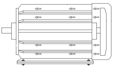 Fig.8. IC411.
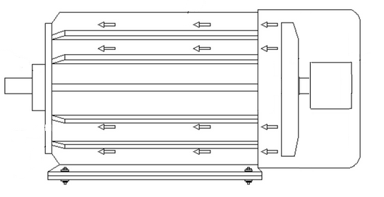 Fig.9. IC416. Note separate motor for
driving the fan.
Fig.9. IC416. Note separate motor for
driving the fan.
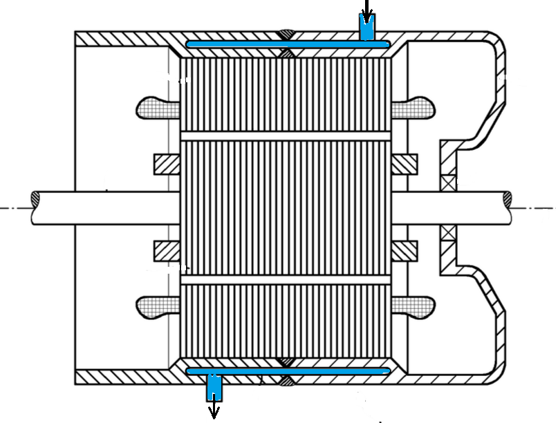 Fig.10. IC71W. Note the cooling mantle.
Fig. 11 shows that IC416 provides more load capacity at low speeds than IC411. It is because the independently fed fan motor of IC416 configuration allows maintaining the cooling air flow independently on the rotor speed.
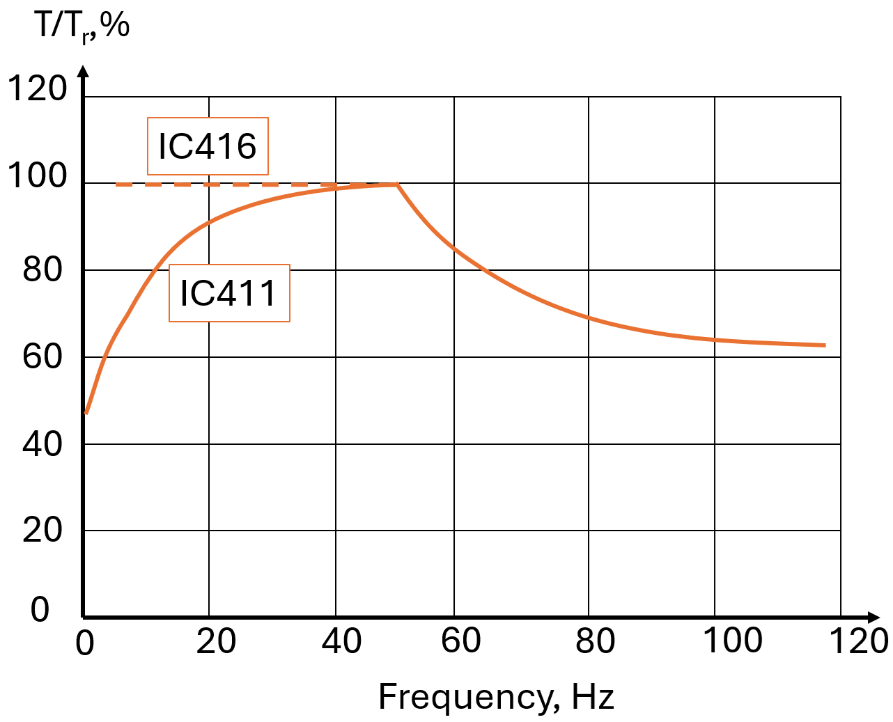 Fig.11. IC411 vs
IC416.
Fig.11. IC411 vs
IC416.
Water-cooled machines can be 20-40% smaller than air-cooled IP54/55 machines. If cooling water is available, some economies in motor size can be obtained by the use of water-cooling.
Mechanical design
Mounting variants
There are three basic variants of mounting included in DriveConstructor: B3 - foot-mounted, B5 - flange-mounted, B35 - machine with both feet and flange. The difference between mounting variants is reflected in price. Flange-mounted machine would have 1-3% higher price and flange&foot-mounted - by 5%, compared to the basic foot-mounted design.
 Fig.12. B3
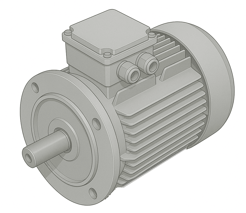 Fig.13. B5
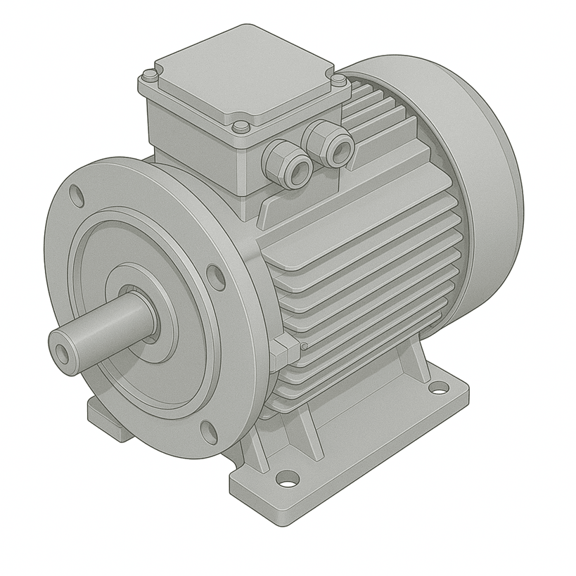 Fig.14. B35
Shaft height
IEC and NEMA has standardized motor dimensions, including shaft height.
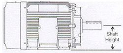 Fig.15. Shaft height
illustration.
Fig.15. Shaft height
illustration.
Standard shaft heights row in mm: 56, 63, 71, 80, 90, 100, 112, 132, 160, 180, 200, 225, 250, 280, 315, 355, 400, 450, 500, 560, 630, 710. If the shaft height of the driven mechanism is set, then it can be beneficial to choose electric machine with the same or close shaft height to simplify coupling of the motor and the mechanism. If the shaft height of the driven mechanism is unknown then for the electric machine "any" can be chosen instead of some concrete value. Shaft height is approximately equal to half the diameter (h=OD/2).
Frame material
The available frame materials are used based on their mechanical strength, density, heat transfer capability, cost, corrosion resistance, etc. In DriveConstructor it is possible to choose from Aluminum (AL), Cast Iron (CI) and Steel (S). Some characteristics of the materials in comparison to the others are given below:
-
Aluminum
-
vs CI&S: Aluminum is almost two-three times lighter than steel or cast iron but several times more expensive
-
vs CI&S: Aluminum is a better heat conductor than steel or cast iron. The extrusion process enhances aluminum's heat conducting properties by allowing the frame sections to have thinner fins placed closer together. The result is more fins and greater surface area for maximum cooling. So, machines with aluminum frames will be more compact and lighter
-
vs CI&S: Machines with aluminum frames are usually cheaper and easier to install (because they are lighter).
-
Cast iron
-
vs AL: Cast iron machines don't have corrosion problems. Their frames are much stronger than aluminum frames, but they are heavier and harder to install.
-
vs S: Cast iron is cheaper than steel
-
Steel
-
vs CI: The yield strength of steel is higher than the ultimate strength of cast iron. This makes steel much stronger and 250% more rigid than cast iron. Cast iron is perceived as a rugged motor frame material because of its bulkiness, when in reality its relatively fragile nature requires 2-1/2 times as much metal to approach the performance of steel. And when it comes to impact loads, steel provides much greater resistance to cracking.
Aluminum frames are usually used up to 60 kW, steel and cast iron frames - to MW level.
Insulation classes
Anyone specifying or using electric machines should have understanding of how the insulation is related to temperature. Three classes of insulation are in common use (with F being the most common):
- class B - with a maximum operating temperature of
- class F - with a maximum operating temperature of
- class H - with a maximum operating temperature of
Typically motors are designed for a maximum ambient temperature of 40 . The difference between the average winding temperature and any hot spot is limited and it is usual to allow a 10 margin for class B and F insulation and a 15 margin for class H.
| Insulation class | B | F | H |
|---|---|---|---|
| Maximum insulation temperature | |||
| Maximum temperature rise |
Note that electrical machines are designed for an overall temperature rise to a level that is below the maximum specified for the insulation materials. For example, using class-F insulation:
max ambient + max temperature rise = ,
which gives a thermal reserve of . The larger the thermal reserve, the longer the life expectancy of the insulation material.
When operating continuously at the maximum rated temperature of its class, the life expectancy of the insulation is about 10 years. Most machines do not operate at such extreme conditions because an additional safety margin is usually allowed between the calculated load torque requirements and the actual size of the machine chosen for the application. So life expectancy of a machine, which is correctly matched to its load and with suitable safety margins, can reasonably be taken between 15 and 25 years. It is common practice to design machines for class-B temperature rise but to actually use class-F insulation materials. This provides an extra thermal that will extend the life expectancy to more than 20 years. This also means that the machine could be used at higher ambient temperatures of up to or more, theoretically up to .
Running motors at a reduced temperature will also significantly extend the useful life. For example, a machine operating at will have an estimated life of
- only 300 hours with Class A insulation
- only 1800 hours with Class B insulation
- only 8500 hours with Class F insulation
- tens of thousands of hours with Class H insulation