Drive systems
Drive systems exercises
SYS-1. Rated speed vs weight, size & cost
For the system driving a pump and consisting of a motor and a frequency converter investigate how chosen rated speed of the machine affects it's weight, size and cost.
Design the system with the following parameters:
- Pump: rated flow 100 l/s, head 110 m, pump efficiency 86%, speed 1050 rpm,
- Motor type SCIM, cooling IC411,
- Grid voltage 400 V.
First choose machine with the synchronous speed of 1000 rpm. Record weight and cost of motor and of frequency converter.
As the alternative variant choose machine with synchronous speed of 1500 rpm. Record weight and cost of motor and of frequency converter.
Compare weights and costs of the two motors (1000 and 1500 rpm), then compare costs of the two systems. Draw conclusions and explain. Can you explain the results/conclusions as electric machine designer?
- [!] Make sure you keep machine type, efficiency class, cooling, protection class and other "influential" parameters constant (the same). Include these parameters in your report.
SYS-2. Design for short and wide speed ranges
The chief engineer is to design drive system for the three similar conveyors with different operational speed ranges. Available information (common for the three conveyors):
- One drum to be driven
- Gearbox: helical 1-stage, ratio 1:5
- No overloads, duty cycle - 100%
- Air-conditioned clean power house, abundant heat removal capability
- Distance between the driven drum of the conveyor and the FC (cable length) - 30 m
- Grid 400 V
- Rated torque 5 kNm
- Cooling: cooling water is not available. Consider the two air-cooling variants: (a) IC411, (b) IC416
Difference between the conveyors: speeds (min-max)
- 1 case: 40 - 200 rpm (wide speed range)
- 2 case: 180 - 200 rpm (narrow speed range)
- 3 case: 180 - 206 rpm (overspeed)
Help the chief engineer to design the three systems. Record weight and cost of motor and of frequency converter for each case. Draw conclusions and explain. Can you explain the results/conclusions as electric machine designer? Converter designer? System designer?
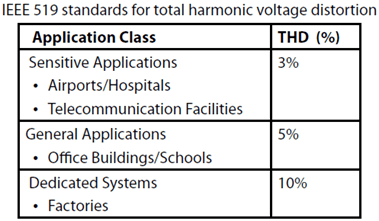
SYS-3. THD
Design drive trains for the three identical pumps for the three application areas: airport, office building and factory. Choose solution with lowest cost. Note that limits in the three above mentioned areas are according to IEEE519 (see table below). Short-circuit power (the same in all three cases): 1000 MVA.
Pump parameters:
- Rated flow 50 l/s, head 200 m, efficiency 81%, speed 1450 rpm
- Grid voltage - 6000 V
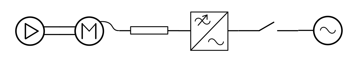
SYS-4. System design
Choose optimal drive train for a pump in water supply system.
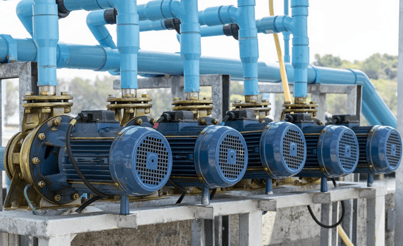
picture source
Parameters:
- Rated flow 50 l/s, head 200 m, pump efficiency 81%, speed 2900 rpm
- Grid voltage 690 V
- Conditions in the electric room, where frequency converter is to be installed: dry environment, good ventilation ensuring heat removal, temperature not exceeding 40 degrees, cooling water is not available
- Distance from the electric room to the pump (cable length) - 50 m
- Conditions at the place of the pump installation, where the motor will be coupled to the pump: some moisture, temperature not exceeding 40 degrees, cooling water is not available
Make and present three design variants:
- 1st variant: design for the lowest system cost
- 2nd variant: design for the highest system efficiency (lowest energy consumption)
- 3rd variant: design for the highest system efficiency with budget constraints on the investment in the new drive system of 39000 Euro
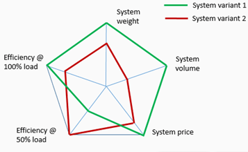
Present benchmarking results as a spider diagram (one of the possible variants shown below). Comment on the diagram.
SYS-5. Influence of gearbox type
Analyze efficiency (at several loads), weight and cost of electromechanical part of drive train (gearbox + electric machine) for the two applications:
Wind turbine
Parameters: Torque 10 kNm, Speed 30 rpm, overspeed 1,2, grid 6000 V.
Compare the following three variants of gearbox stages and electric machines: (1) Pl+Pl+Hel+SCIM vs (2) Pl+Pl+Hel+PMSM vs (3) Pl+Pl+PMSM, where "Pl" means planetary gear stage, "Hel" means helical gear stage.
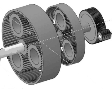 Fig.1. Gearbox with 2
planetary stages and one helical stage - "Pl+Pl+Hel" (Source: Romax).
Fig.1. Gearbox with 2
planetary stages and one helical stage - "Pl+Pl+Hel" (Source: Romax).
Conveyor
Parameters: Torque 10 kNm, Speed 200-300 rpm, grid 400 V.
Compare the following three variants of gearbox stages and electric machines: (1) Worm+SCIM vs (2) Hel+Hel+SCIM vs (3) Hel+Bevel+SCIM, where "Worm" means worm gearbox.
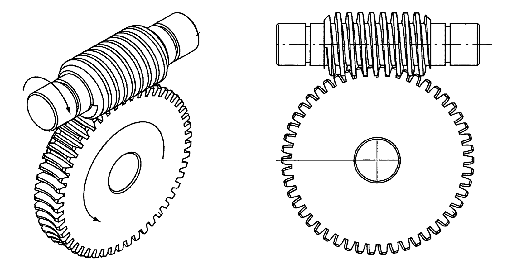 Fig.2. Gearbox with 1 worm stage -
"Worm".
Fig.2. Gearbox with 1 worm stage -
"Worm".
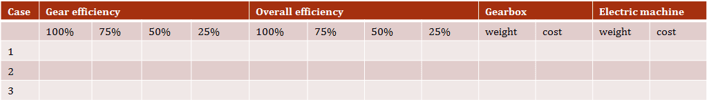
Reflect on efficiency if operation is at partial load most of the time. Collect results in the tables (separate table for each application).
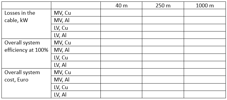
SYS-6. Filters, cable length and losses
Design drive trains for four pumps (all have identical parameters: flow 250 l/s, head 280 m, efficiency 87%, rated speed 1450 rpm). Distance to the respective pumps from the electric room (with 6 kV voltage source) where the system driving the pumps are installed: 40 m, 250 m, 1000 m.
Try systems with LV and MV FC.
First, set cable on "automatic selection". Then try higher and lower cross-sections and different number of runs. Compare the results. Try both copper and aluminum as the cable material. Compare the results. Summarize your findings in a table.